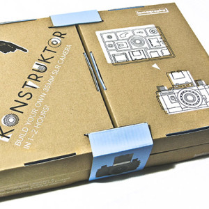
So the guys at Lomography laid down the big challenge – build it yourself. The latest gee whiz idea from perhaps the maddest camera company on Earth is a build-it-yourself kit SLR, an irresistible experience and toy. So I did. And what I found was that some of their instructions were, well, missing. So here is my take on assembling the beast. I’ve done a little camera maintenance and repair so I’m no dummy and I know what the bits should do – but I know my limitations too and the tough stuff goes to a proper technician. My images, such as they are, and the full story, are in the January 2013 issue of Australian Photography + digital.
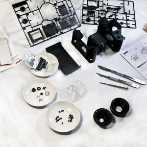
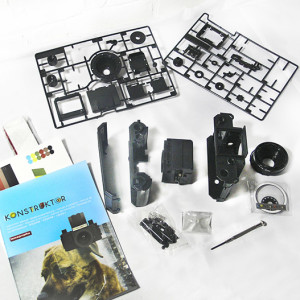
Staring at the bits The Konstruktor is packed in a unique roll-folding box with boxes within the box. Inside you’ll find a couple of parts frames, familiar to any plastic model builder – parts have to be broken out of the frame.
The Konstruktor Box.
There is an instruction book of course and the main part of the camera itself is in five parts – back, chassis, mirror box assembly, front shell and lens tube. There is also a bag of small parts, a bag of clear plastic parts and a bag of larger parts like the lens ring sticker and nameplate. Finally you find the manual, a sheet of stickers, a pack with the leatherette covers. and – a screwdriver. It’s not exactly Ikea!
The basic contents unpacked. Body parts including the mirror box assembly, the grids, the packages of small parts and the manual.
The acid test here was to see whether I could do a decent assembly with just the screwdriver provided or whether I’d have to use the proper toolkit and possibly even a little glue and tape? The answer is no – the screwdriver is not enough. It’s not even good enough for the job. There are a couple of things that you need to know and do which are not in the guide/manual. I won’t go into excruciating detail here as you do need to be reasonably practical to complete it but I can save you a little time and grief at a couple of points.
Assembly Tools provided: One magnetised Phillips head screwdriver. It’s a bit inadequate as you are driving self-tapping screws into virgin plastic and I soon went to the toolkit for a #0 with a larger handle. You will also need a sharp knife for cutting and scraping. I use scalpels but a typical hobby knife or a one sided razor blade (as used in those little paint scrapers) will do just fine.
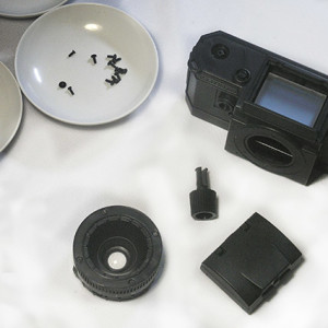
Beginning the lens assembly. Note the division of the four types of screws and the additional tools – sharp knives!
You will need a lubricant as well – see below – and a little sandpaper perhaps – 120-240 grit is fine. Finally you can manage without a pair of needle nose tweezers but they are very useful for picking up and placing screws and pulling the springs. So is a bit of tape to hold a couple of things in place as you assemble. I prefer green masking tape or medical tape (Micropore) as they peel off nicely.
When you open the box you should lay out the body parts in order. The Lomography people have cheated for you – the mirror box, a tricky assembly, is already done. It looks odd because of the shutter type – a black plate faces the lens mount – but that’s fine. At this point, use the tweezers to peel off the blue plastic protective cover on the mirror – the instructions never mention this. It’s easier now and does no harm. Be careful not to scratch the mirror – there is a little bit of ‘fold over’ to get a grip.
The manual does not identify the different screws – yes it calls them S1-4 in the assembly (there are four kinds) but the S numbers in the parts list are used for the sticky covers! Open the little clear plastic bag (point of no return) and empty the contents into a small dish. There are some small shutter parts – remove to a separate dish for later. That leaves you with a pile of screws and four springs, two very small.
There are four types of screw – separate them: • S1 – five small countersunk screws (cone head) – four are used for the front of the lens, step 02. The fifth is a spare. • S2 – seven ‘pan head’ screws – they have a large disc head as if they have a washer attached. These are for holding down cogs that need to turn. Two spares. • S3 – 12 larger mushroom head screws. These are the main construction screws. Three spares. • S4 – three small mushroom head screws. Two are used in the first step, 01, to hold the lens rings together. One spare.
When you begin assembly, you soon get to the two grids – the lens is on one of them! It’s not really possible to ‘break them out’ – use a hobby knife or blade to cut at least some of the attachment points and then to trim the remaining break points if you’re fussy. It’s not necessary but it’s…nicer. Also be careful about numbering – the parts are all numbered by tabs in the same gap as the part but sometimes it’s in a confusing place around the corner – the lens is a good example.
When I put the lens together – Panic. Tight fit. It would not turn without real effort. I tried sanding down the four tapering guides inside just a little but still stiff. It needs a lubricant but regular light oil is messy and a potential plastic solvent!
I used Dri-Lube, a stick of hard lubricant you get in hardware stores for lubricating saw blades, car door catches, etc. But you can go Russian traditional – they often used candle wax in lenses; a little rubbed on the inner barrel does it. If it’s still too tight, sand down the guides gently – it should be tight but turn smoothly. Oh, and when you push in the front ring (A8) make sure that it seats right down on the barrel properly before driving in the four countersunk screws – that took me a couple of tries and a firm push.
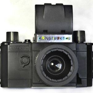
The major assemblies completed - the lens, viewfinder and body.
The viewfinder is straightforward. I spray painted the top cover black before I started . The little magnifier (in the bag with the focus screen) must go in so it folds downwards – it is possible to fit it upside down. The front of the base is the open side – so that it can slide on to the body. When finished, it should all close down with a firm click – back first then the side plates fold in right side, then left or it won’t close properly.
The next step is the hardest. You have to assemble film advance cogs and part of it is spring loaded. You need to drop the larger spring with a hook over a post on the body. You then need to pull the hook around (tweezers) and drop the cam P8 on to the post so that the spring hooks on to the right projection. If you get it right, the cam will flick back into place when you pull on it. Next the film advance spindle drops in and you have to put the large toothed wheel P4 into the slot at the bottom of the body so that the spindle goes through its middle. It’s in position when the top of the spindle seats down well and the spring loaded cam connects with a tooth underneath the top disc.
Next the film take-up tube goes in and it has to be push down firmly into the hole at the bottom – it does not float loose. The large cog P1 drops into the top of it, unsecured and finally the small cog P9 is screwed down in position. It’s all working properly if when you turn the cogs, the cam slowly moves across and locks the main cog – this allows the film to advance and lock in position for each frame.
The shutter assembly is the next tricky bit – the little odd shaped cam has to be fitted and although it has little holes in the two arms, they connect to nothing. This attaches to the front switch for B and N (bulb and instant), the two shutter speeds. Then attach one of those tiny springs B10 to the body post, long arm upwards and hanging down – push it on firmly. The shutter cam then screws on with three pan head screws and should slid easily. Catch the hanging end of the spring (tweezers!) and hook on to the post on the sliding shutter cam. If it goes ‘ping’ and disappears into the carpet on the other side of the room, or if you mangle it, don’t panic – you have a spare!
Then all you have to do is clip the four body parts together in the right orientation - it’s held by two screws in the side. Don’t forget the tripod nut - I did – so upside down is best. The viewfinder screen has to be held on top of the mirror box with a finger or bit of tape – shiny side up and don’t touch the dull side! You can wipe fingerprints off the shiny side afterwards.
Attach the top knobs. The shutter button seems low until you realise that there’s a shutter button cover they forgot to mention – just push it firmly into place. Slide on the viewfinder hood and once you’ve attached the shutter cocking lever (step 28) you can push it up and fire the shutter. The mirror comes down into place and flicks up when you fire. At last it really is a reflex camera. Attach the lens and check that it clicks into place and focuses smoothly (or disassemble it and adjust!)
Completed to lock-up stage. At this point you can load and shoot to test.
Aftermath • Number of parts I dropped on the floor and recovered: two (no screws or springs). • Number of times I had to disassemble to go back a step: three (well four if you include three attempts at putting the body together – forgot the tripod mount nut so those two screws had to come out again!) That’s a pretty good score. Number of leftover bits: at least one of each screw, three of the main type and a spare shutter spring.
This is a bit unnerving. if I work on a camera, leftovers afterwards are a worry but these are genuine spare parts! Other redundant parts: three sets of body leatherette covers are provided; red, white and black.
Time taken: just over two hours but I was stopping to take pics and write notes. I think I could do a second one in less than an hour!
Cosmetic improvements. Any model shop can provide suitable stuff – spray paint for the body has to be paint that ‘keys’ to plastic and they have spray cans in every colour. Spray paint the front body shell, back cover and viewfinder cover before assembly if you intend to do this. My local newsagent had paint pains – they look like markers but have enamel paint in them in many colour – including pink (groan). They’re good for small areas like ridges. I tested all these on the leftover grid frames for grip and finish. Nice leatherette can be found on those spectacle cases you find in charity shops for a dollar or less – one case has enough for more than one body – cut and peel. Glue on with a contact adhesive but test first (I use a specialist rubber cement, Pliobond, which is only available in the USA but again, model shops will have a non-solvent type glue). You can use a good double sided tape if you want to change your mind – two layers.
Problems The film wind started to jam up after each shot – it would not advance. I discovered that if I depressed the shutter button before cocking the shutter, it would release the wind mechanism and I could wind on. This self-corrected by the second film so perhaps a cog or ratchet bedded into place properly by them. The shutter selector jammed at first as well so I only had N (Instant – 1/80th) and no Bulb. This also freed up halfway through the second film and flicked over a little too easily so I ended up with a grossly overexposed section in the middle of the film. I may tape it in position.
It takes ages to rewind the film so be careful that it really is all rewound (yup, made that mistake). It is also a good idea when you’ve just loaded to backwind the film just a little to tension it. But not much – there is no rewind lock and you could wind it back into the cassette! Close the back, wind and fire twice and then hold the advance knob and wind back until the film is tight.
There is no focus point indicator on the body although the distance is marked on the lens. Turn the lens to infinity and then put a small dot on the body next to the inf. symbol. Then you can see what focus range you’ve selected. You cant rely on the finder – it’s too small and even with the magnifier, seeing the point of focus is almost impossible.
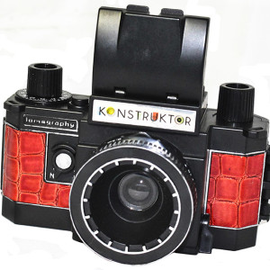
My Konstruktor, finished with red snake vinyl I found on a spectacle case. I used the supplied covers as a template. The silver trim paint proved too fragile and wore off quickly - a better alternative will need to be found.

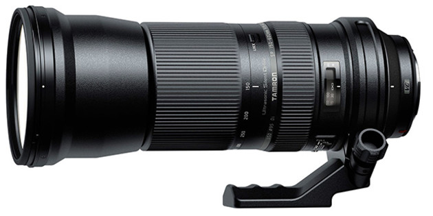 Tamron's latest telephoto zoom extends to a massive range of 150-600mm, making it ideal for sports, nature and wildlife photography.


